Radio World -
by Harold Hallikainen
San Luis Obispo, Calif. In the last article in this series, we looked at how a complex impedance can be represented as a magnitude and phase in polar form, or a real part and an imaginary part in rectangular form. Table 1 presents the complex impedance of the basic components in both forms. In this table, R is resistance in ohms, and X is reactance in ohms. j is the square root of -1, but for our purposes right now, we just use it to identify the imaginary part of a complex number (the real part has no j, the imaginary part does have a j term).
| Component | Rectangular | Polar |
| Resistor | R+j0 | R/ 0 |
| Inductor | 0+jXL | XL/ 90 |
| Capacitor | 0-jXC | XC/ -90 |
In the last article we also found that multiplication and division of complex numbers in polar form is quite easy. For multiplication, we just multiply the magnitudes and add the phase angles. For division, we divide the magnitudes and subtract the phase angles. For addition and subtraction of complex numbers, however, it's easier if we go back to rectangular form (R+jX). To add two complex numbers, add the real parts to get the real part of the result, then add the imaginary parts to get the imaginary part of the result. Subtraction is pretty much the same, but the signs change. Table 2 summarizes these methods.
| Addition | (A+jB) + (C+jD) = (A+C) + j(B+D) |
| Subtraction | (A+jB) - (C+jD) = (A-C) + j(B-D) |
| Multiplication | (A/ B) * (C/ D) = (A*C) / (B+D) |
| Division | (A/ B) / (C/ D) = (A/C) / (B-D) |

Finally, we need a way to convert back and forth between rectangular and polar coordinates. Some calculators know how to do it on their own, but we'll look at the basic trigonometry here.
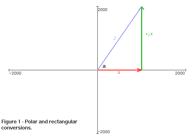
Referring to figure 1, we see complex impedance that can be expressed as either R+jX (rectangular form) or Z/ a (polar form of Z at angle a). If we start with rectangular form (R+jX) and want polar (Z/ a), we can determine the magnitude (Z) using the Pythagorean theorem (a special case of the law of cosines first described by Pythagoras about 500 BC). A right traingle having sides R and X will have a hypotenuse (Z) of sqrt(R2+X2). From basic trig, the definition of the tangent is "opposite over adjacent." So, the tangent of angle a is X/R. To find a, we take the "arctangent" or "inverse tangent" (tan-1) of X/R.
Also referring to figure 1, we can convert from polar to rectangular by using the trig definitions of sine (abbreviated sin) and cosine (abbreviated cos). The sine of an angle is defined as "opposite over hypotenuse", so sin a = X/Z. The cosine of an angle is defined as adjacent over hypotenuse, so cos a = R/Z . Multiplying each of these terms by Z results in X and R, which we need for the rectangular representation of impedance. Table 3 summarizes the conversion formulae.
| A/ B = (A cos B) + j(A sin B) |
| A+jB = sqrt(A2+B2) / tan-1B/A |

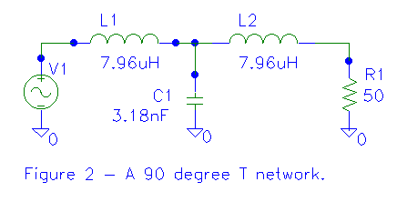
Finally, let's apply our knowledge to analyze a 90 degree lag T network, similar to that found at the base of an AM tower. This circuit is a low-pass filter that is generally used for impedance matching. Its behavior is similar to a 90 degree length of transmission line (which we'll look at a little later). As a transmission line, the T network as a "characteristic impedance". If the output is terminated in an impedance matching the characteristic impedance, the input impedance will match the load impedance. More generally, ZO=sqrt(Zin2+ZL2). We can use this formula to easily determine the characteristic impedance (ZO) of a 90 degree network to match a desired load impedance (ZL) to a desired input inpedance (Zin). To make a 90 degree network, we just use inductors and capacitors whose reactance at the frequency of interest is equal to the characteristic impedance. Figure 2 shows a 90 degree T network that matches 50 ohms to 50 ohms (useful!) while providing a 90 degree lagging phase shift. The reactances were calculated for operation at 1 MHz.
Let's determine the input impedance "seen" by V1. Recall that in this circuit all the reactances are 50 ohms, so the impedance of the inductors is 0+j50 or 50/ 90. Further, the impedance of the capacitor is 0-j50 or 50/ -90, and the impedance of the resistor is 50+j0 or 50/ 0. Let's do a step by step calculation of the input impedance.
L2 and R1 form a series circuit, so the equivalent impedance is just the sum of the individual impedances. Recalling that we add in rectangular form, we find the equivalent impedance of L2 and R1 is
(50+j0) + (0+j50)
50+j50
70.71/ 45
In the last step we converted to polar form since we are anticipating needing to multiply or divide. C1 is in parallel with this impedance. We can determine the equivalent impedance of this series-parallel circuit using the same techniques we used for DC. We can use either the "product over sum" or "reciprocal of the sum of the reciprocals" methods. The second method converts each impedance to its reciprocal (its admittance), adding the admittances of the parallel components, then coverting the resulting admittance back to impedance by taking its reciprocal. This approach works for any number of parallel components. The "product over sum" approach is an algebraic simplification of the two parallel component reciprocal method. For some reason my students favor this method even though the reciprocal method is more general (less formulae to memorize!) and involves fewer calculator keystrokes, since our calculators have 1/x keys. We'll try using the reciprocal method where we start by adding admittances. We determine the admittances by taking the reciprocal of the impedance (dividing the impedance into 1/ 0).
YT = Y1 + Y2
YT = (1/ 0 )/(50/ -90) + (1/ 0)/(70.71/ 45)
YT = 20e-3/ 90 + 14.14e-3/ -45
Converting to rectangular form to do the addition...
YT = (0+j20e-3) + (10e-3-j10e-3)
YT = 10e-3 + j10e-3
Converting back to polar to invert admittance back to impedance...
YT = 14.14e-3/ 45
ZT = (1/ 0)/(14.14e-3/ 45)
ZT = 70.7/ -45
And converting back to rectangular to do some addition...
ZT = 50-j50
The above impedance is the equivalent impedance of C1 in parallel with the series combination of L2 and R1. When we add L1 in series with this impedance, we get the input impedance to the network.
Zin = (0+j50) + (50 - j50)
Zin = 50 + j0 = 50 / 0
So, the input impedance is the same as the output impedance. This is what we expect when a 50 ohm 90 degree network (or transmission line) is terminated in its characteristic impedance. Let's take a quick qualitative look at what happens as the load impedance varies. Assume the load is zero ohms (a short). We find L2 directly in parallel with C2, forming a parallel resonant circuit (since the impedance of the capacitor is 0-j50 and the impedance of the inductor is 0+j50). This parallel resonant circuit has (ideally) infinite impedance. If we then put L1 in series with this infinite impedance, we still have infinite impedance. The network looks like an open circuit when the output is shorted.
How about if we don't connect a load to the output (leave it open)? In that case, L2 can be ignored (since the right half isn't connected to anything) and L1 and C1 now form a series resonant circuit whose impedance is zero ohms. Terminating the network in an open circuit results in a zero ohm input. Just like a 90 degree transmission line!
We'll play around with this circuit a bit more next time. 'til then, stay tuned (to 1/(2*pi*sqrt(L*C)).
Harold Hallikainen designs transmitter control and lighting equipment for Dove Systems, a manufacturer serving the broadcast and entertainment industries. He also teaches electronics at Cuesta College and is an avid contra dancer. He can be reached at +1 805 541 0200 (voice), +1 805 541 0201 (fax), harold@hallikainen.com (email), and http://hallikainen.com (World Wide Web, where an archive of these articles is maintained).